Well this format suites me reasonably well
First and foremost SAFETY
The parts shown here are Galvanized pipe. I chose this over Black pipe because it photographs better, do not follow this lead. The problem with Galvanized pipe is when welded or sufficiently heated it burns off zinc in the form of zincoxide this stuff is toxic to breathe. I used considerable caution and extreme countermeasures to elieveate this danger, save your self-the trouble, use black pipe it is safer by far and often cheaper.
CAPTIONS AT BOTTOM OF PICTURES.
This is the pre welding appearance of my first manifold. The section between the bell reducer and the reducing bushing is a 1.5 inch short nipple with 6 evenly spaced #55 holes drilled in it. Plates were added later that span and completely cover the section between bushing and bell. The flats of the bushing were used as a form and the plates, made of 1/4 crs were Migwelded in place and sealed air tight except for a 3/8 hole in one plate that then received a welded on pipe fitting for 1/8 npt this constituted the air gas mixer.
It should be noted that the air gas Mixer above is way more complicated than necessary, many people use a simple hole at the mid point of a tube with good results.
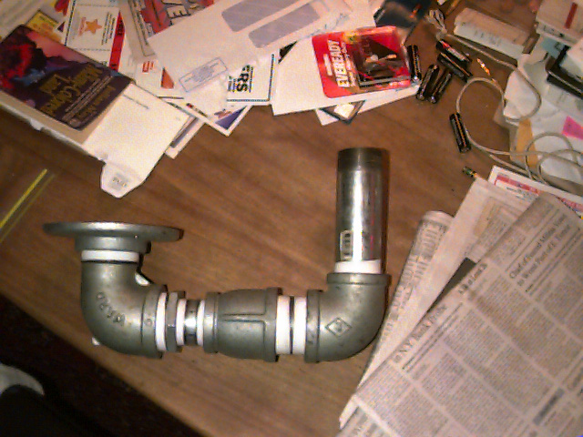
The parts shown here are:
1 2" floor flange
1 2" 90deg street elbow
1 2" to 1.5" reducing Bushing
1 1.5" short nipple
1 2" to 1.5"bell reducer
1 2" short nipple
1 2" standard 90drg elbow
1 2"x12" pipe
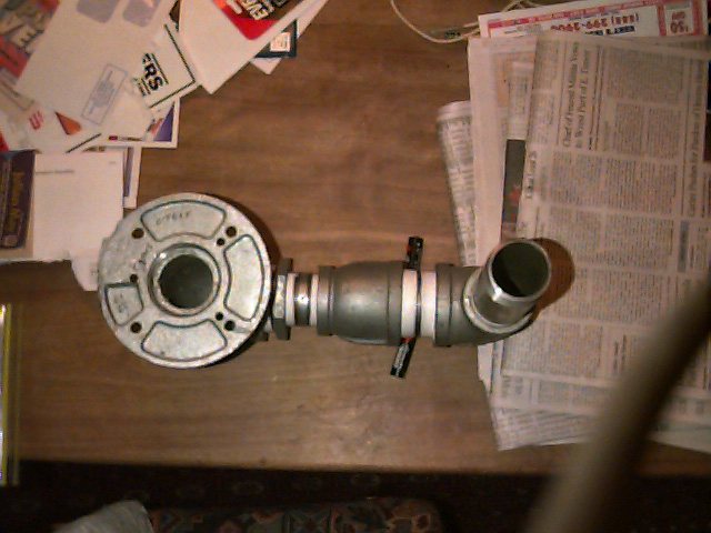
This is a dorsal view if you will of the same assembly. The 4 large holes in the floor flange are the ones that it was born with. The 3 smaller ones I made for the studs to mount the blower. Studs hmm rather I welded bolts to it after slipping them through the holes. The bolts were qty 3 1/4-20 x 1+"
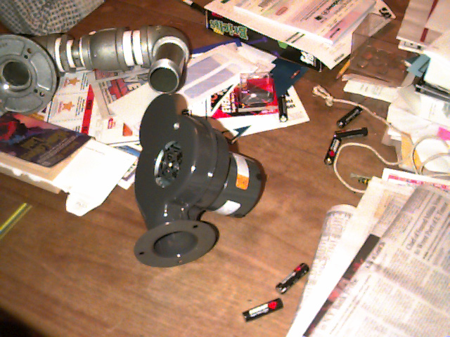
Here is the blower I got mine at Grainger but any similar unit would work.
Specks: 60cfm @ 120VAC
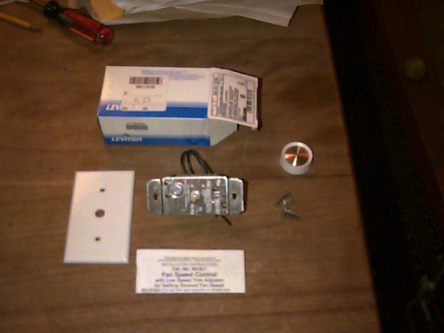
I felt that it might be desirable to have some control over the fan so this simple control was added, again from Grainger.
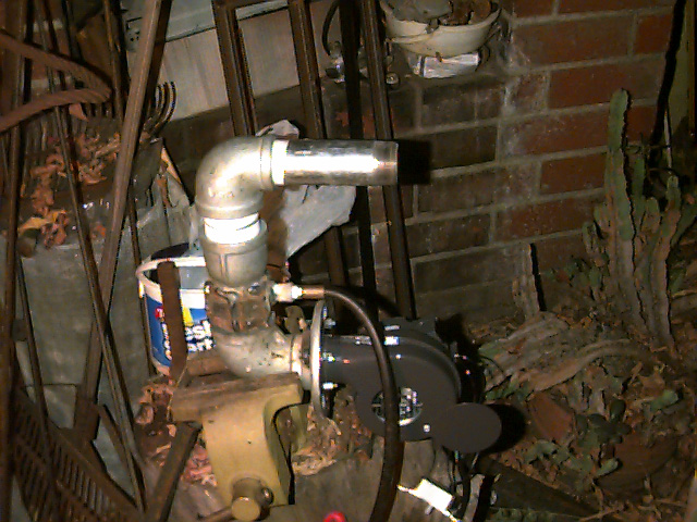
Ok here it is assembled. This design did fire and did achieve the goal of compactness but it tended to backfire and puff out and flutter etc. The problem is with a short bent manifold is that there is insufficient moving air mass to insure a steady flame, 60cfm blower or not.
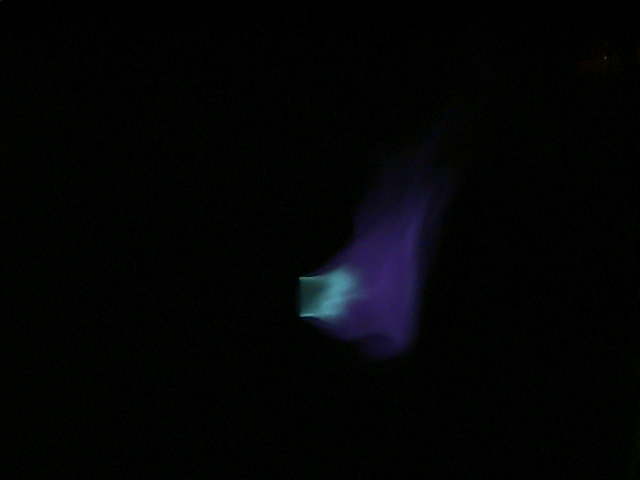
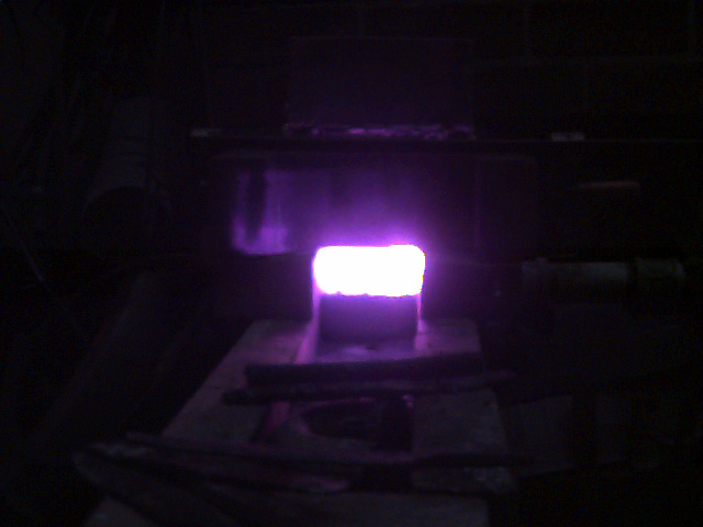
Here is a nice neutral flame from the burner above set at absolute lowest and slowest burn.
NEXT:
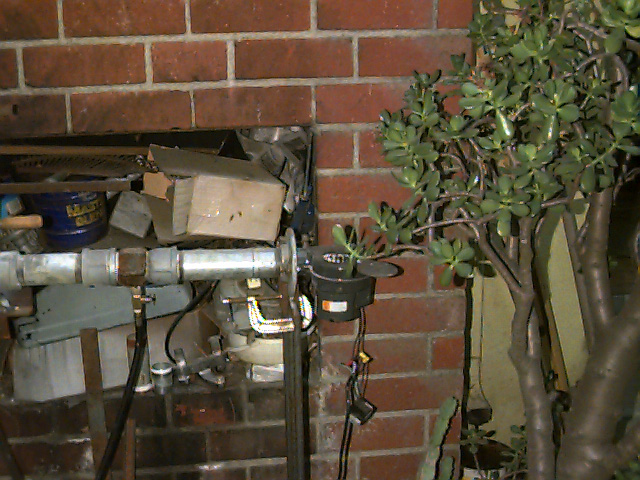
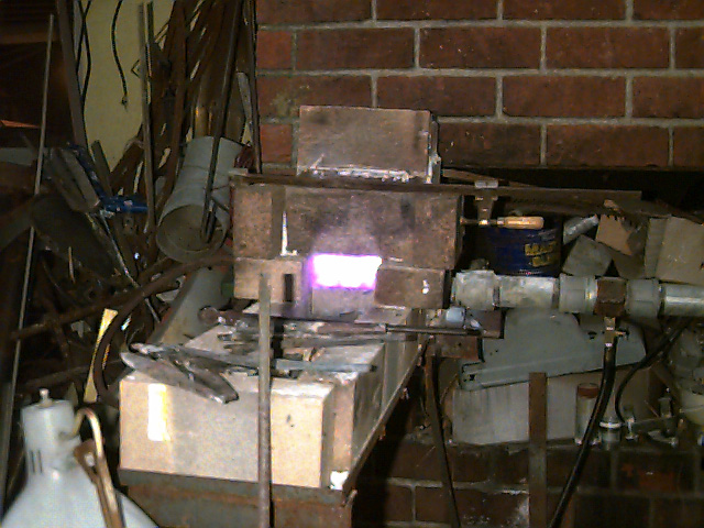
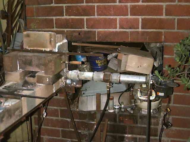
The New design employs a more straightforward approach, notice same mixer, that’s a valve below the mixer for metering the gas, I later added a regulator from a roofing torch. I highly recommend a regulator of some kind. This Unit performs very well, and is still in use, or will be when I make it a new box.
This size is about as small as you can go at this level of technology, tuned manifolds etc could be shorter and much more costly.
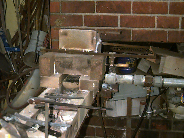
Well here be the box, this picture is with the glue drying, an experiment that worked but was nonetheless a bad idea. Burning paintable silicon (water based carrier) stinks to high heaven, yes it does cook off to a decent insulating crack fill, but it is not worth it. This box is made of "Fire Brick" from a local brickyard, cost $0.67ea. Yes those are work pieces in the foreground, I did say that the bent unit worked, just not reliably.
Once the glue sat a wile I would hasten the process a little. There are 2 small work pieces in there but the camera is a tad bit limited. This is not full heat for this unit, full heat as I was to find became a problem.
This is full heat, and those cheep bricks are melting, yes melting, also I found them to be very thermally inefficient. I burned allot of propane just warming the bricks up and keeping them that way. Better bricks and insulation are available from major kiln/ceramics supply Houses I am using Laguna Clay.
Well that’s about it for now, I have a few other pictures (better views etc)
Last shot, it is to bad that the bricks were so bad the rest of it really did work quite well.